

Where roads and highways cross steep terrain, it is important to ensure that the stability of road cuts and road embankments is ensured. Further is required to divert flow of water from slopes such that the road is not an obstruction for the water flow, and that the groundwater level is not too shallow below the pavement of the road. Natural landslides may also be present and may cause instability of the road itself, road cuts, and embankments. Consequences of instable road cuts and embankments may be failure of the road, be dangerous, and may make the road unusable (Figure 1). This use case provides an appreciation of the basic concepts behind the analyses and design of a road where it crosses steep terrain (Figure 2). In order to illustrate the conceptual approach, an example from the Belmont area on St Vincent is used.
Use case intended for: Engineer
Keywords:
Road cut, embankment, road engineering, slope stability
| Before you start: | Use case Location: | Uses GIS data: | Authors: |
|---|---|---|---|
|
To carry out some of the analysis in this use case, it is required to have engineering geological and geotechnical engineering skills, and have a basic knowledge of road engineering in order to be able to analyse the implications of roads crossing steep terrain. In steep terrain roads may be affected by various processes related to flash floods and natural slope stability (i.e. landslides). An example of this is given in Use case 3.2.3 "Roads in landslide affected areas". This Use case 3.3.3 "Landslide mitigation measures for roads" discusses the possible mitigation measures. Hence, preliminary to the mitigation measures discussed in this use case, a study as described in use case 3.2.3 should be executed. |
St. Vincent | No | Robert Hack |
Introduction:
Roads crossing steep terrain often require the construction of road cuts and embankments. This to make horizontal space available for the road. The road cuts and embankments should be made such that these are stable up to the end of engineering lifetime of the road, i.e. up to the end of the time the road has to serve its purpose for traffic. Roads in steep terrain also may be subject to natural slope instability (i.e. landslides) and water flow from slopes, e.g. drainage water and flash floods. These are not discussed in this use case, but in use case 3.2.3 "Roads in landslide affected areas". This Use case 3.3.3 "Landslide mitigation measures for roads" gives an example of the possible mitigation measures for road cuts and embankments. Hence, preliminary to the mitigation measures discussed in this use case a study as described in use case 3.2.3 should be executed.
Mitigation measures for instable road cuts and instable embankments are various and depend on local conditions and the size and type of landslide or slope failure. This use case discusses the Belmont area (St Vincent) where road cut stability and embankment problems occur.
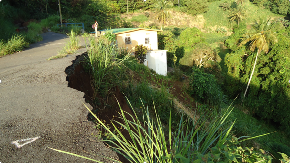
Figure 1: Belmont area, St Vincent. Embankment failure (Image credit: Hack, 2014)
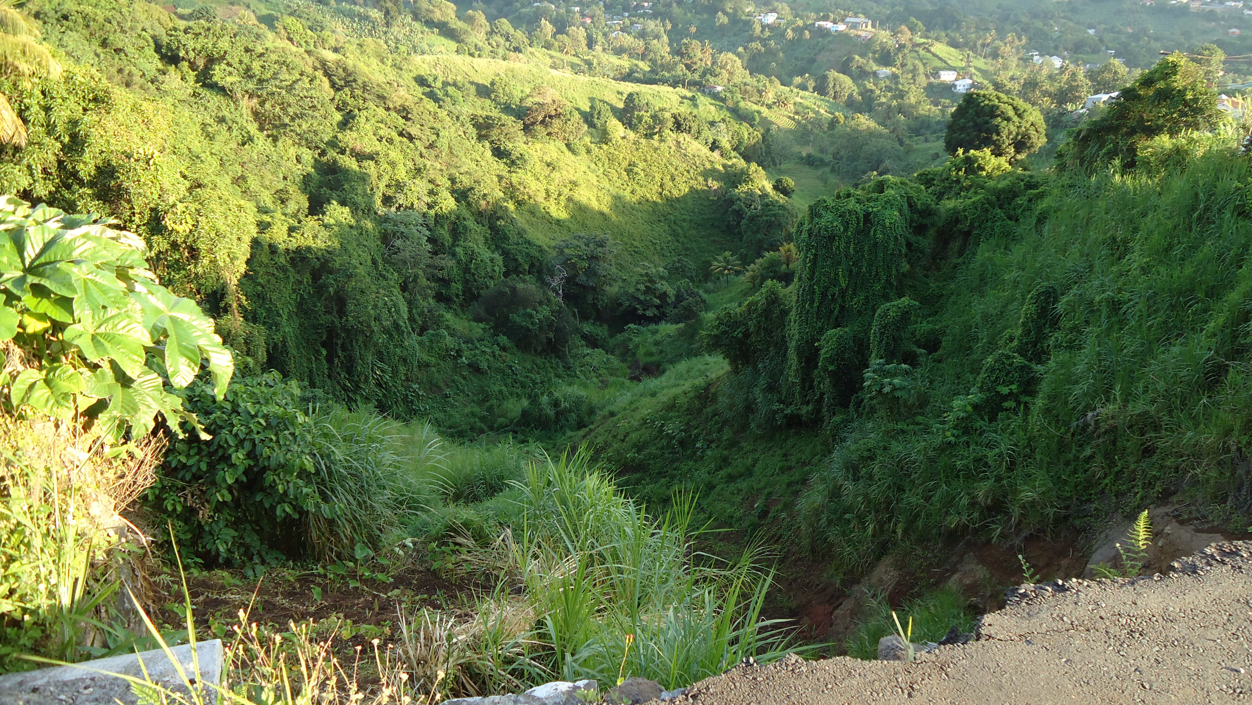
Figure 2: Belmont area, St Vincent. Steep terrain (Image credit: Hack, 2014)
Objectives:
Determine mitigation measures for the future stability of road cuts and embankments along a road.
Flowchart:
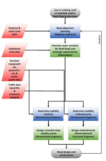
Simple Flowchart
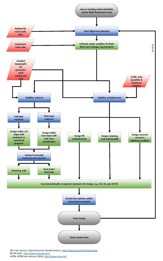
Detailed Flowchart
Use case study area description:
Geology
The island of St Vincent belongs to the chain of volcanic islands forming the Lesser Antilles Island Arc. This is the surface feature of the subduction of the North American Plate beneath the Caribbean Plate, which was initiated in the early lower Eocene (Smith et al., 1980). Generally, the geology of the island is volcanic. The southern part consists of weathered and deeply dissected eroded volcanic breccias and basaltic lava flows, in some places as dykes. The northern part consists of relatively less weathered andesite lavas, interbedded with pyroclastic deposits of the Soufriere eruptions (Hay, 1959). The island has generally an even distribution of porphyritic and olivine bearing andesite lava flows and pyroclastics (Hay, 1960; Rowley, 1978b). In some areas, e.g. the South-East Volcanics, lavas dominate while in other areas, e.g. the Grand Bonhomme Volcanic Centre, volcaniclastic deposits (Figure 3) (Robertson, 2003a). Pyroclastics ash deposits are the most abundant volcanic products on the island. Ash particles vary in fragment size from fine to coarse, and in some places consist of lapilli, bombs, and blocks. It is estimated that 55% of the island is covered by blanket deposits of well-bedded pyroclastic ash of the yellow tephra formations, resulting from the eruptions of the Soufrière volcano during the late Pleistocene (Rowley, 1978a). The deposits are generally andesitic with varying compositions of lithic and vitric, and have variable degrees of weathering. Other deposits present on the island include agglomerates which are andesitic and basaltic in composition, alluvial deposits, and reworked pyroclastic, agglomerates, volcaniclastic, volcanic ash, and scoria deposits.
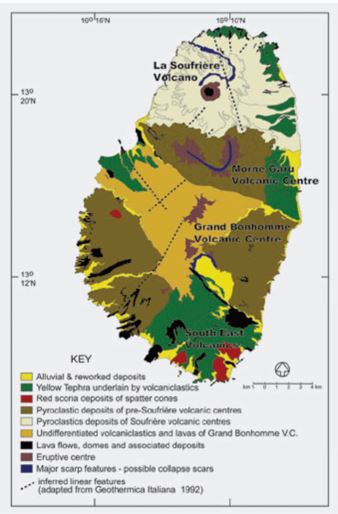
Figure 3: Geology of St. Vincent (after Robertson, 2003b).
Local geology
The local geology in the area of the use case, the Belmont area, consists of slightly to completely weathered bedrock of irregular series of pyroclastics and volcaniclastics, partially or in patches overlain by a blanket deposit ash (tuff) layer. The topsoil is mostly relatively thin and generally less than 0.5 m.
Problems definition and specifications:
If a road has to cross steep terrain, flat horizontal areas have to be made to allow a flat road to be constructed. A flat horizontal area is normally made by excavating a "road cut" in the uphill side of the road and using the material from the excavation to make an embankment on the downhill side of the road (Figure 4). The road is then constructed partially on the flat area created by the road cut and partially on the embankment. Ideally the quantity of material excavated from the road cut is in balance with the quantity of material necessary for the embankment, avoiding long distance transport.
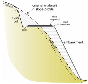
Figure 4: Road construction in mountainous terrain. The material excavated in the road cut is used as fill for the embankment.
The materials on a natural slope in mountainous terrain are normally weathered under influence of the hydrosphere, e.g. rainfall, groundwater, and day-night temperature changes. Commonly, this forms a top soil layer of residual material from weathered bed soil and rock mixed with slope debris from higher up on the slope (Figure 4). The groundmass (i.e. rocks and/or soil) below the topsoil will also have been weathered to a certain depth below the surface of the groundmass. The depth of the weathered zone depends on the type of minerals, the texture and structure of the groundmass, and the history of the slope. The history includes how long the groundmass on the slope has been exposed to the hydrosphere, the change in steepness of the slope due to geological heave or subsidence of the mountain, processes such as erosion and landslides removing weathered groundmass revealing fresher groundmass, and influence by man, animals, and vegetation. The geotechnical properties of the weathered material are normally less than those of fresh groundmass material.
The natural slopes are normally at a stability of unity in the situation as applying during the last worst possible conditions. Any material that was not at equilibrium at that time will have slit of. The worst possible conditions may be heavy rain, an earthquake, or worse both at the same time. The latter is not unlikely in a volcanic environment as volcanic eruptions are often associated with heavy rain due to ash in the air, and with earthquakes. Since the time of the last event, weathering will have progressed and groundmass properties been reduced.
Making a road cut increases the dip angle of the slope, hence the constructed road cut has a steeper angle than the natural slope angle. However, when making the road cut, the topsoil and weathered material underneath have been excavated leaving fresher and thus geotechnically better material forming the road cut. Therefore, often the road cut is more stable at the time of excavation than the original natural slope.
The materials excavated in the road cut are normally used for the embankment (Figure 4). In principle the topsoil layer and weathered material excavated from the road cut should not be used for the embankment because of its poorer geotechnical properties. However, experience learns, that often also the weathered material has been used in the embankment even such that the weathered material, being excavated first, is first dumped on the side of the embankment. In this way the weakest materials form the basis of the embankment.
With time the newly exposed materials in the road cut and the material in the embankment will (further) weather with as consequence a reduction in geotechnical properties and thus in stability. This will often go unnoticed for some time, until an event triggers failure. In addition, also the natural slopes weathers further and material on the natural slopes may become unstable. This may cause landslides affecting the road during worst conditions.
During rainfall water may run over the slope and also over the road (flash floods). Water over the road is not wanted because it makes the road slippery and erodes the pavement. More important, water on the pavement or directly below the pavement creates excess pore water pressures in the basement and pavement, causing a rapid degradation of the road and cracks and potholes in the pavement. Therefore a ditch should be present on the uphill side of the road allowing diversion of the water flowing from the slope.
The design of road cuts and embankments should be done and should have been done for existing road cuts and embankments, following standards and construction codes state-of-the-art at the time of construction. For example those published by the International Organization for Standardization (ISO, 2015), ASTM International (formerly American Society for Testing and Materials) (ASTM International, 2015), and the British Standards Institution (BSI, 2015). Many tens of different standards and codes are applicable to slope and embankment design and construction. However, the materials dealt with are natural materials with all variation, inhomogeneity, and peculiars inherent to natural materials. This makes that the standards and codes refer many decisions about design and construction to the "engineering judgement" of the design and construction engineers. Moreover, weathering being quite important in road construction in a mountainous terrain, may be a good described feature qualitatively, but quantitative factors for estimating the influence of future weathering on the geotechnical properties of natural materials over the full lifetime of the construction are seldom published in the literature and are not given in the standards and codes.
Additionally, financial constrains may have been a reason for the design and construction engineers to defer from ideal practices and take decisions may not have been optimal for the stability of road cut and embankments over the full engineering lifetime of the structure.
The above description shows that designing road cuts and embankments in a mountainous terrain and applying mitigation measures for instable natural slopes, road cuts, and embankments are complicated. This requires the engineers to have a decent background in geotechnical engineering and engineering geology, besides the necessity to execute an extensive site investigation including boreholes and in-situ and laboratory testing, to investigate and quantify geotechnical properties of natural materials. In the context of this use case, only a limited "walk-over" site investigation has been done. Simple visual descriptions of the materials on site and some simple field test have been done. In this use case is shown how mitigation measures are recommended based on this limited site investigation, and when it is advisable to obtain more detailed site investigation data.
Data requirements:
Topographical maps on scale 1:10,000 are required for routing of roads. More detailed topographical maps are required for design and construction and for mitigation measures such as maps with scales ranging from 1:1,000 to 1:100. These maps are best to be supplemented by a Lidar or leveled point maps with a minimum spatial resolution in the order of 0.2 m in length and width and with height information in the order of centimeters.
Further are required (the scales are ideal requirements):
On a site scale (meters to tens of meters):
- Detailed geological and geotechnical information
- Type of soil and rock masses and mineral content; the latter to be able to assess the future weathering of the soil and rocks.
On a 1:100,000 scale:
- Climate, prevailing wind directions, and rainfall data; to be able to assess the future weathering of the soils and rocks, to access quantities of water to be expected to run-off over the topography, and to be able to assess variations in groundwater level, if groundwater level data during and after heavy rainfall is not available.
- Groundwater level data
- Earthquake data; including intensity or peak acceleration - frequency maps
- Traffic intensity data
Analysis steps:
These analysis steps apply equally to both new road planning and the redevelopment of existing roads, although for redevelopment, mitigation options may be more limited.
1. Visual inspection and reconnaissance (typically the responsibility of a Highway Engineer)
A site should be visually inspected on topography, geology, quantity of rain and surface water (flash floods, drainage) (see Methodology Book), the quality of existing roads if any, intensity of traffic, and slope stability on various scales. This is illustrated in use case 3.2.3 "Roads in landslide affected areas".
Actions to be taken (by Highway Engineer):
1a. Site visit
2. Determine the necessity of mitigation measures (typically the responsibility of a Highway Engineer with assistance of geotechnical specialist as indicated)
2a. Flash Floods
Mitigation methods for flash floods are a proper draining and maintenance of drainage facilities. Water running-off over the road pavement should be prevented, but also the groundwater level and water level in the basement of a road should be such that buoyancy of pavement and ground material are avoided and no excess pore water pressures should occur as these may cause a very rapid degradation of road pavement (see use case 3.3.4 "Flood mitigation for road").
In the Belmont area mostly drainage ditches are present at the up-slope side of the roads, however, these are partially filled with debris and vegetation (Figure 5). The ditches have to be cleaned. The size of drainage ditches may be assessed based on calculations of rainfall and run-off water over the slope above the road (see Methodology Book) or by questioning the local residents whether the existing ditches at the location are sufficient. If not size and depth should be increased. Calculation of size of drainage facilities makes only sense if sufficiently detailed rainfall and run-off data is available for the local situation.
Actions to be taken (by Highway Engineer):
2a1. Obtain rain data and flash flood data from actual detailed measured data, or by questioning local residents of the area.
2a2. Inspect local roads on evidence of pavement degradation, i.e. cracks, crack patterns, potholes, and side erosion, i.e. locations of extruding groundwater, due to too high groundwater levels (see Methodology Book).
2a3. Determine whether existing drainage is sufficient, new artificial drainage should be constructed, or existing artificial drainage should be renovated and, if necessary, be enlarged.
2a4. Design drainage following appropriate accepted standards, e.g. ISO, ASTM, and BSI (see Methodology Book).
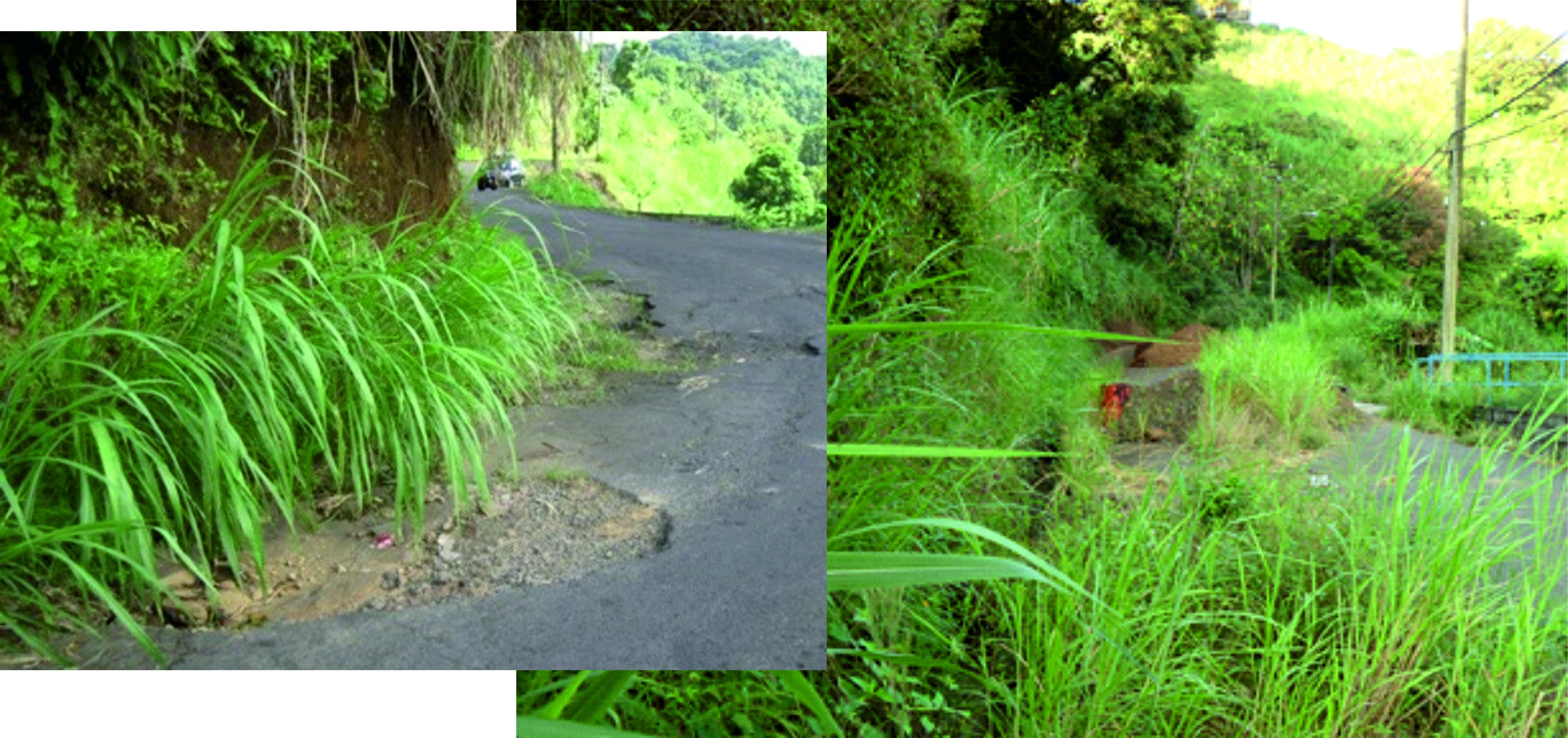
Figure 5: Belmont area, St Vincent. Drainage ditches along road partly filled by debris and vegetation (image credits, left: WB, 2016; right: Hack, 2014)
2b. Sediment carried and transported in flash floods and run-off water
Sediment may be carried and transported by flash floods and run-off water. Sediment transported on and over the pavement may be a nuisance but may also be dangerous (see Use case 3.2.3 "Roads in landslide affected areas"). Further it may interfere with the drainage of the road. Hence, quantities of expected sediment should be determined. Measured data on sediment quantities are seldom, and mostly the engineer will have to make a studied guess. In the Belmont area, the quantity of sediment carried by the run-off water is not very much at present and does not likely require special measures, apart from regular maintenance (cleaning of ditches).
Actions to be taken (by Highway Engineer):
2b1. Guess the quantity of sediment in flash floods and run-of water.
2b2. Clean ditches or if required, design ditches and drainage such that sediment does not block drainage.
2c. Landslides and embankments
In a mountainous areas always a risk exists that a new road construction triggers new landslides or re-activates existing natural landslides due to the often required embankments and road cuts to be made. The embankments and road cuts should be properly designed such that these are stable, form no risk for the road users, and also not for the users lower down or higher up on the slopes below and above the road.
The Belmont area is clearly instable for a long time. Many larger and smaller displacements are visible in the landscape. Likely the displacements are as well caused by natural landslides as by man-induced landslides and by man-made slopes and embankments. However the displacement in the road seems not to be largely influenced by the natural or man-induced landslides. The road in the area (Mespo Highway) has been made by cutting into the slopes above the road and dumping materials below the road as embankment. Both have increased instability of the slopes above as well as below the road (Figures 1, 6 and 8).
Figure 6: Belmont area, St Vincent. Embankment failure (image credit: Hack, 2014).
The embankment at one location failed and slit. The plane on which the failure occurred is very steep (Figure 7). Mitigation measures can be various; a new embankment made by dumped material, a retaining wall with backfill, or a concrete structure. An embankment made by dumped material may require large quantities of material and be high. The slope is steep which may make construction of an embankment with properly compacted dumped material difficult. Material suitable for embankment fill should preferably consist of granular permeable material that does not weather in the environment. This material is likely not available or has to be transported over long distance and is thus expensive. Using locally available material may result in an embankment of irregular sized material, partially rock in various degrees of weathering mixed or in patches with likely weathered material resulting from tuff and topsoil. Problem with these materials is the susceptibility to weathering after being dumped, hence it is likely that geotechnical properties of the embankment material will degrade because volcanic materials are prone to very rapid degradation at surface.
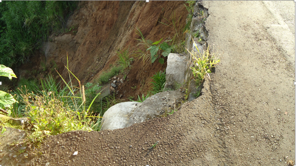
Figure 7: Belmont area, St Vincent. Steep failure plane of embankment failure (image credit: Hack, 2014)
An alternative to an embankment is a retaining structure consisting of bricks or concrete with backfill. For the backfill material similar considerations should be taken into account as for an embankment without retaining structure; weathering may degrade the properties of the fill. For the dumped embankment and the backfill behind a retaining structure should be considered that local material may already contain large quantities of clay minerals and that further weathering is likely to increase the quantity of clay minerals resulting in a further reduction of permeability of the embankment and fill materials with time. Pore water pressure in the embankment and fill materials, and water pressure behind retaining structures should then be taken into account for design at present, but also that these problems are likely to increase over the engineering lifetime of the embankment.
Permeable geotextile is sometimes used to give horizontal reinforcement to embankments and fills behind retaining walls, or to allow drainage trough the geotextile. Geotextiles are sometimes also applied as restrain behind gabion walls to reduce wash out of finer materials trough the wall. Geotextiles work very well in granular material with little or no clay fraction, but with larger quantities of clay, the geotextile may get clogged and becomes impermeable. As stated above the local available materials contain clay minerals which quantity is likely to increase with time. An impermeable geotextile will act as barrier for water and will cause built up of water pressures in the embankment or behind the retaining structure, which may lead to failure.
A concrete structure for example a plateau on piers (piles) may well be a suitable and on the long-term more attractive alternative to embankments or retaining structures with backfill. The piles of the structure should be properly positioned into the bedrock into drilled holes to a sufficient depth into preferably sound and unweathered bedrock. If sound and unweathered bedrock is not reached within acceptable depth, it may be decided to found the piles in less sound and weathered rock if design bearing capacity per pile is reduced. Geotechnical properties of more shallow depth material are also likely to reduce with time due to weathering. This should be taken into account in design.
Actions to be taken (by Highway Engineer):
2c1. Inspect topography on steepness, evidence of subsurface displacements indicating landslides and slope instability, i.e. steps in landscape, escarpments and scarps, based on visual inspection, available satellite and aerial imagery, and topographical and geomorphological maps. Question local residents on evidence of surface and subsurface displacements.
2c2. Determine the ground- and surface water regime (see Methodology Book).
2c3. Inspect local housing, roads, and other structures on cracks or deformation (i.e. differential settlement and rotation) that may indicate movements in the subsurface.
Actions to be taken (by Highway Engineer with assistance of geotechnical specialist):
2c4. Check detailed local geology and geotechnical data with available geological, geotechnical, and geomorphological maps. The detailed local data should be checked minimally on meter scale, but in some occasions it may be necessary to check on centimeter- or decimeter scale. If existing maps are not suitable (outdated, insufficient scale or accuracy, or otherwise not suitable) sketch a new geological/geotechnical map on an appropriate scale for the project, on top of satellite or aerial imagery. It should be noted that in particular any feature that may determine stability negatively is mapped. For example, even millimeter or centimeter thin clay layers may cause a slope to be unstable. The presence and detailed location of such small features is thus required information in the geotechnical analysis and should be mapped.
2c5. Define the geotechnical units in the subsurface in the area. Geotechnical units are units in which the geotechnical properties are more or less homogeneous, including weathering and discontinuity properties.
2c6. Determine subsurface boundaries between the different geotechnical units based on a priori knowledge of the geology of the area, surface exposures, boreholes, penetration testing, trial pits, etc.
2c7. Determine properties of the geotechnical units based on surface exposures, borehole and penetration test data, groundwater levels, and laboratory test data, and on the data obtained from the points above such as visual inspection and cracks in existing structures.
2c8. Determine future properties of the materials in the geotechnical units. Volcanic materials are often prone to very rapid weathering such as forming of clay minerals that may reduce geotechnical properties, for example, reduce effective angle of internal friction and permeability.
2c9. Built a three-dimensional subsurface model including the geotechnical units with properties. A three-dimensional model may be made in a computer model, but can also consist of a series of long- and cross-sections of the subsurface.
2c10. Calculate stability of area and road location based on the model of the step before. Take into account the possible degradation of geotechnical properties due to weathering.
2c11. If mitigation measures require fill materials, check present and future properties of available fill material.
2c12. Design mitigation measures and re-calculate, and repeat this step until a satisfactory outcome in technical, social, environmental, and economic values (see Methodology Book). If possible and feasible incorporate measures to reduce weathering rates such as isolation of the soil and rock from the atmosphere, by covering of the soil and rock with layers of soil, gunite or shotcrete, or reduction of percolating groundwater by using drainage ditches, layers of soil, or geotextile to reduce inflow of water at top of slope.
2d. Road cuts on uphill side of the road
Roads in mountainous terrain often require road cuts to be made. The slopes of these road cuts should be properly designed such that these are stable, form no risk for the road users and also not for the users higher up on the slope above the road. In the Belmont area, the road cuts in bedrock and tuff along the road have a limited height up to a couple of meters (Figure 8). However, even a relatively small road cut of low-height in a groundmass removes the support for the slope above. Especially on steep slopes, this may cause relaxation of the mass above the road resulting in opening of existing and new discontinuities (i.e. joints) and the mass loses structural integrity. Moreover, the discontinuities will allow increased water percolation through the groundmass that increase weathering rates for the mass above the road. Especially volcanic materials may degrade very rapidly due to weathering. The higher the road cut the more relaxation will occur. Whether this is a problem depends on the use of the slope above. In the Belmont area the use consists of housing and some agriculture. In particular houses built on piles may suffer of relaxation of groundmass around the foundation, e.g. loose bearing capacity and move outwards on the slope, endangering the houses. Mitigation measures are various ranging from making the road cuts less steep and less high to bolting, anchoring, retaining walls, and/or shotcrete. Making the road cuts less high implies that the existing road has to be shifted outside with respect to the natural slope. This is likely not feasible as this will be expensive. Alternatives are however expensive too, but should be considered. Doing nothing will likely result in movements in all slopes above the road with the consequences as described above.
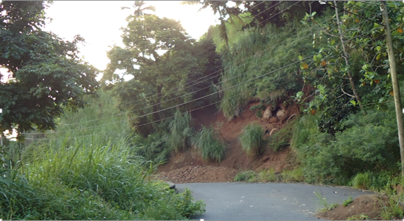
Figure 8: Belmont area, St Vincent. Slopes above the rock are degrading and show signs of instability (image credit: Hack, 2014).
Bio protection of slopes, road cuts, and embankments
Bio protection of slopes is a proven method to reduce erosion of the surface layers of road cuts and embankments. By reducing erosion also weathering of underlying layers is reduced. However, it should be noted that this applies to types of vegetation with shallow rooting. Any larger vegetation with normally deeper reaching roots may increase instability as the roots form entry points for atmospheric water and air into soil and rock masses, and the roots cause widening of existing and new discontinuities (i.e. joints) in the mass, reducing the strength of the mass. Some vegetation may also produce acids and other fluids that cause the soil and rock masses to degrade. Therefore, the road cuts and embankments in the Belmont area should be covered by grass-type or small scrub vegetation with preferably roots growing superficially just below the surface of the slope. Any larger vegetation should be removed. Construction engineers should select the plants that fulfill the requirements, already grow in the neighborhood, and are proven not to become a biological hazard. Introducing vegetation from elsewhere on the island or from other islands or continents may be very hazardous as this could lead to biological disasters. Removing larger bushes and trees from the slope may lead to (partial) deforestation. Analyses should be performed on the aesthetical, biological, and environmental consequences and balance the consequences against the costs of measures such as re-routing the road or extra stabilizing measures. Experimental measures may be the use of "bio-grout" that based on bacterial action may form a crust layer on the outside of the slope which improves stability and may protect underlying material from weathering (DeJong et al., 2013; Van Paassen et al., 2010).
Actions to be taken (by Highway Engineer):
2d1. Inspect topography on steepness, evidence of subsurface displacements indicating landslides and slope instability, i.e. steps in landscape, escarpments and scarps, based on visual inspection, available satellite and aerial imagery, and topographical and geomorphological maps. Question local residents on evidence of subsurface displacements.
2d2. Determine the ground- and surface water regime.
2d3. Inspect local housing, roads, and other structures on cracks or deformation (i.e. differential settlement and rotation) that may indicate movements in the subsurface.
Actions to be taken (by Highway Engineer with assistance of geotechnical specialist):
2d4. Check detailed local geology and geotechnical data with available geological, geotechnical, and geomorphological maps. The detailed local data should be checked minimally on meter scale, but in some occasions it may be necessary to check on centimeter- or decimeter scale. If existing maps are not suitable (outdated, insufficient scale or accuracy, or otherwise not suitable) sketch a new geological/geotechnical map on an appropriate scale for the project, on top of satellite or aerial imagery. It should be noted that in particular any feature that may determine stability negatively is mapped. For example, even millimeter or centimeter thin clay layers may cause a slope to be unstable. The presence and detailed location of such small features is thus required information in the geotechnical analysis and should be mapped.
2d5. Define the geotechnical units in the subsurface in the area. Geotechnical units are units in which the geotechnical properties are more or less homogeneous, including weathering and discontinuity properties.
2d6. Determine subsurface boundaries between the different geotechnical units based on a priori knowledge on the geology of the area, boreholes, penetration testing, trial pits, etc.
2d7. Determine properties of the geotechnical units based on surface exposures, borehole and penetration test data, groundwater levels, and laboratory test data, and on the data obtained from the points above such as visual inspection and cracks in existing structures.
2d8. Determine future properties of the materials in the geotechnical units. Volcanic materials are often prone to very rapid weathering such as forming of clay minerals which may reduce permeability of materials.
2d9. Built a three-dimensional subsurface model including the geotechnical units with properties. A three-dimensional model may be made in computer model, but can also consist of a series of long- and cross-sections of the subsurface.
2d10. Design and calculate stability of road cuts based on the model of the step before. Take into account the possible degradation of geotechnical properties due to weathering.
2d11. Design mitigation measures for improving slope stability and re-calculate slope stability, and repeat this step until a satisfactory outcome in technical, social, environmental, and economic values (see Methodology Book). If possible and feasible include measures to reduce weathering rates such as isolation of the soil and rock from the atmosphere, by covering of the soil and rock with layers of soil, gunite or shotcrete, or reduction of percolating groundwater by using drainage ditches, layers of soil, or geotextile to reduce inflow of water at top of slope.
Results:
The results should be a design of road cuts and embankments.
Conclusions:
Improper designed road cuts and embankments in mountainous terrain are very often a source of future problems. Properly designed mitigation measures may in first instance seem expensive, however on the long run these are mostly far cheaper than the mitigation measures required when large volumes of slope masses have lost integrity and started moving.
References:
ASTM International, 2015. ASTM International (formerly American Society for Testing and Materials). West Conshohocken, PA, USA. http://www.astm.org/ [Accessed: 15 December 2015]
BSI, 2015. British Standards Institution (BSI). BSI, London. http://www.bsigroup.com/ [Accessed: 15 December 2015]
DeJong, J.T., Soga, K., Kavazanjian, E., Burns, S., Van Paassen, L.A., Al Qabany, A., Aydilek, A., Bang, S.S., Burbank, M., Caslake, L.F., Chen, C.Y., Cheng, X., Chu, J., Ciurli, S., Esnault-Filet, A., Fauriel, S., Hamdan, N., Hata, T., Inagaki, Y., Jefferis, S., Kuo, M., Laloui, L., Larrahondo, J., Manning, D.A.C., Martinez, B., Montoya, B.M., Nelson, D.C., Palomino, A., Renforth, P., Santamarina, J.C., Seagren, E.A., Tanyu, B., Tsesarsky, M. & Weaver, T., 2013. Biogeochemical processes and geotechnical applications: progress, opportunities and challenges. Géotechnique. 63 (4). DOI: 10.1680/geot.SIP13.P.017. ISSN: 0016-8505. pp. 287–301.
Hay, R.L., 1959. Origin and weathering of late Pleistocene ash deposits on St. Vincent, B.W.I. The Journal of Geology. 67 (1). pp. 65-87.
Hay, R.L., 1960. Rate of clay formation and mineral alteration in a 4000-year-old volcanic ash soil on Saint Vincent, B.W.I. American Journal of Science. 258 (5). DOI: 10.2475/ajs.258.5.354. pp. 354-368.
ISO, 2015. International Organization for Standardization (ISO). Geneva, Switzerland. http://www.iso.org/ [Accessed: 15 December 2015]
Robertson, R.E.A., 2003a. Making use of geology-the relevance of geology and geological Information to the development process in St Vincent and the Grenadines. In: St Vincent and the Grenadines Country Conference, St Vincent, 22-24 May 2003. The University of the West Indies, School of Continuing Studies, p. online. http://www.open.uwi.edu/sites/default/files/bnccde/svg/conference/papers ... [Accessed: 11 May 2015]
Robertson, R.E.A., 2003b. The volcanic geology of the pre-Soufrière rocks of St Vincent, West Indies. PhD thesis. Mona, University of the West Indies, Kingston, Jamaica
Rowley, K.C., 1978a. Late Pleistocene pyroclastic deposits of Soufrière Volcano, St. Vincent, West Indies. Geological Society of America Bulletin. 89 (6). DOI: 10.1130/0016-7606(1978)89<825:LPPDOS>2.0.CO;2. pp. 825-835,.
Rowley, K.C., 1978b. Stratigraphy and geochemistry of the Soufriere Volcano, St. Vincent, West Indies. PhD thesis. Seismic Research Unit, University of the West Indies, St. Augustine, Trinidad. p. 282.
Smith, A.L., Roobol, M.J. & Gunn, B.M., 1980. The lesser antilles — A discussion of the Island arc magmatism. Bulletin Volcanologique. 43 (2). DOI: 10.1007/BF02598033. ISSN: 0366-483x. pp. 287-302.
Van Paassen, L.A., Daza, C.M., Staal, M., Sorokin, D.Y., Van der Zon, W. & Van Loosdrecht, M.C.M., 2010. Potential soil reinforcement by biological denitrification. Ecological Engineering. 36 (2). DOI: 10.1016/j.ecoleng.2009.03.026. ISSN: 0925-8574. pp. 168-175.